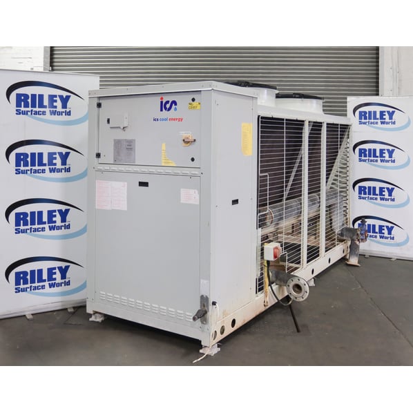
Industrial Cooling Systems (ICS) AT/K P2055 Industrial Chiller


- Stock No
- CE657
- Manufacturer
- Industrial Cooling Systems (ICS)
- Model
- AT/K P2055
- Year of Manufacture
- 2018
- Serial
- 32092830
- Condition
- From a working environment, Good Condition, Current Model
- Ave. cooling capacity
- Cooling Power 187kW
- Ave. Water Flow Rate
- 12.0/42.0M3/Hr
- Other Info
- Refrigerant R410A
- Location
- Our Central Warehouse, Aldridge, UK
- Weight (kgs)
- 980
- External Dimensions (WxDxH mm) [?]
- 1500 x 3370 x 2100mm
- Delivery Your delivery options
Description
The fully packaged, EcoDesign compliant, air-cooled chiller, the AT/K P2055 is designed specifically for reliable and efficient process cooling. The ICS air blast cooler system uses a dry air cooler with a 3-way valve to divert and cool the process fluid in a conventional chiller system.
The i-Chiller Range
The unique evaporator is immersed within a generously sized storage tank. This design ensures safe and reliable operation even during large fluctuations in cooling demand – something often encountered within various industrial applications.
Each unit comes with a 3-bar pump as standard with the option to customise with a 5-bar pump – allowing for demanding industrial applications.
Energy & Process Efficiency
- High efficiency finned coil in-tank evaporator with copper tubes & aluminium fins allowing for variable flow rates
- Hydraulic circuit includes integral 3-bar pump, drain valve, overflow & water pressure gauge and process connections
- Scroll compressor(s) operating with R410a refrigerant.
- Copper tube / aluminium fin condenser coils combined with axial condenser fan
- High efficiency aluminium finned and copper tube heat exchanger
- Optimised air flow paths
- Energy efficient variable speed electrically commutated (EC) Fans
- Non-Ferrous process fluid circuit
Reliability
- Internal water bypass to protect pump against dead heading
- Phase monitor to protect the unit against phase loss & reversal
- Galvanised, epoxy coated carbon steel structure
- Electrical panel protection rating: IP44
Ease of Operation & Maintenance
- High & low refrigerant pressure gauges & switches
- Easy to use and externally visible advanced electronic controller
- Digital input for remote on/off control
- Volt-free contacts for remote general alarm signal
- Mains isolator
- Manual filling kit comprising atmospheric (open) expansion tank
Features Include
- Atmospheric fill & vent tank
- Remote on/off
- Volt free alarm contact
- Water pressure gauge
- High/Low pressure safety switch
- Antifreeze protection
- Outlet temperature indication
- Condensing pressure fan switch
- Tank level sensor
- Alarm history
- Automatic compressor rotation
- High pressure transducers
- High condensing pressure compressor unloading function
- Low ambient to -20°C
- High efficiency brushless axial fans
- P5 High pressure pump
- Run / standby pumps
- Phase cut fan speed controller
- Anti-floodback
- Water filter
- Manual bypass
- Pressure relief bypass
- Compressor soft start
- Electronic expansion valve
- Condensers coil coating
- Pre Heat inline heater
- Trace heating for frost protection
- Manual bypass
- Pressure relief bypass
- Pressurisation kit
- Advanced remote control
- RS485 Modbus trend
- Gateway Modbus trend
- WEB Supervisor with GPRS
- Remote X
- Master/Slave modularity kit
- Glycol filling kit
Specification
- Cooling Capacity 187kW
- Fluid type Water / MPG
- Glycol concentration 30%
- External ambient temperature 28°C
- Evaporator ambient temperature 19°C
- Evaporator outlet temperature 14°C
- Evaporator fluid flow rate 9.05 Litres/Sec.
- Evaporator pressure drop 89.6kPa.
- Total absorbed power 50.6kW
- EER 3.7
- Evaporator type Plate
- Minimum flow rate 4.25 Litres/Sec.
- Maximum flow rate 10.9 Litres/Sec.
- 2 off Scroll compressor
- R410A refrigerant 14Kg charge
- Single cooling circuit
- Oil charge 13Kg
Operation Specification
(1) Evaporator outlet / inlet temperatures +15°C/+20°C, external ambient temperature +25°C, total absorbed power includes compressors & fans
(2) Evaporator outlet / inlet temperatures +7°C/+12°C, external ambient temperature +35°C, total absorbed power includes compressors & fans
(3) Standard unit configuration operating with evaporator outlet / inlet temperatures +15/+20°C
(4) Protection class IP54
(5) Minimum / maximum water flow rates achievable by pump
(6) Available head pressure at outlet of unit at the minimum / maximum water flow rates
(7) Sound power determined on basis of measurements taken in accordance with ISO 3744. Sound pressure at 10m average value obtained in free field on a reflective surface at 10m distance from the side of the condenser coils & at a height of 1.6m from the unit support base. Values with tolerance ± 2dB. The sound levels refer to unit operation under full load in nominal conditions.
Unless otherwise specified, the above data refers to unit configuration with standard axial fans & fitted with standard P3 pump. Data declared according to UNI EN 14511-2013.
SEPR HT: Data declared in compliance with the European Regulation (EU) 2016/2281 with regard to eco design requirements for cooling products and high temperature process chillers.
Fully Supported by OEMs
![]() ICS Cooling placed and supported this cell and cooling machinery with seller. They are available for installation, support and spares.
ICS Cooling placed and supported this cell and cooling machinery with seller. They are available for installation, support and spares.
Transtherm Cooling has offered advice and spares for their Air Blast Cooler.
For the complete package including the Air Blast Cooler see stock number CE657A
![]() Print / Download Industrial Cooling Systems (ICS) AT/K P2055 Industrial Chiller Datasheet
Print / Download Industrial Cooling Systems (ICS) AT/K P2055 Industrial Chiller Datasheet
Photographs taken prior refurbishment. Our refurbishment service is not available on all machines.
Machines & equipment for sale
- Surface Treatment
- Cleaning & Degreasing
- Polishing & Belt Linishing
- Mass Finishing
- Ovens & Furnaces
- Process Cooling
- Shot Blasting
- Dust & Fume Extraction
- Air Compressors
- Rectifiers & Transformers
- Miscellaneous
- Latest Stock
- Special Offers
- Direct From Site Clearances
- Auctions
- Brand New Machines
- Available Immediately
- Sell Your Machine
Machine Alert
Get the latest machines emailed directly to you as they become available to buy online. Sign Up Now