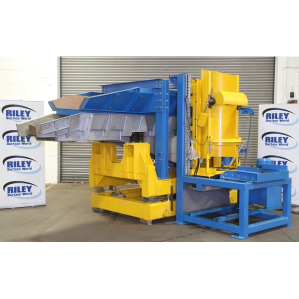
Foundry Projects Ltd One Tonne Capacity Mobile Vibratory Charging System


- Stock No
- VC2224S
- Manufacturer
- Foundry Projects Ltd
- Model
- Travelling Vibratory Charger
- Year of Manufacture
- 2016
- Serial
- 002S1620A
- Condition
- Excellent Condition, Ex demonstration, Current Model
- Capacity
- One Tonne c/w Tipping Drum Loader
- Type
- Vibratory also Powered Travel
- Other Info
- Multiple Materials or Parts Loader
- Location
- Our Central Warehouse, Aldridge, UK
- External Dimensions (WxDxH mm) [?]
- 1620 x 4600 x 2320mm
- Delivery Your delivery options
Description
Comprising of one 1Tonne capacity static drum tilter and one 1Tonne capacity mobile vibratory furnace charging machine with on board load cells. The system is complete with one main control panel and one remote control panel.
£95,000.00 when NEW, only used for demonstration, please see video for operation.
This machine was sold in 2024 to a EU based company commercialising an R&D project processing specialist stainless steel alloys. |
General Plant Description
The scrap copper will be in the form of fragmented copper wire which has been shredded into small pieces and will be delivered to the charging machine by forklift truck in 45 gallon oil drums which are approximately ¾ full having a total weight in the region of 1 Tonne.
The concept of the charging system is based on using a static drum tilter which is used to pour copper scrap from a standard drum into a mobile charging machine travelling on a pair of rails which is used to weigh and vibrate the scrap into an electric furnace (supplied by others). The drum discharge system will work by tipping the drum hydraulically to discharge the contents into the mobile charger. The mobile charger is a vibratory conveying system for moving the scrap into the furnace in a controlled manner and minimising any damage to the furnace crucible. This is done by using a finely controlled feed rate and side deflectors on the discharge chute. The system is designed to accept, hold and deliver the scrap in 1T batches.
The drum discharge system comprises of a base frame incorporating a roller track delivery system, a support assembly to create a main pivot mechanism, a rotating drum location and transfer chute with latching system and loading roller track, a hydraulic tilting system with power pack and two cylinders. An existing site forklift truck will place the drum onto the loading/unloading free running roller track on the system base frame and an operator will then push the drum from the roller track into the loading frame also having a free running roller track to engage the drum into a discharge position which will be latched into that position. An operator will have a hold on control to raise and tilt the drum to discharge it into the charging machine. Once fully discharged the drum will return back to its lowered position again by hold on control which on completion of its stroke can be collected by the forklift truck. The system is hydraulic powered and fully interlocked with the charging machine.
The charger is now storing the 1Tonne of copper ready for travelling to and discharge into the furnace. The charger basically comprises of a mobile carriage, a weighing system, a load cell weigh frame, a vibratory conveyor supported on eight springs and a loading / storage hopper. The vibratory feeder is driven by a pair of contra-rotating out of balance motors controlled through an inverter for frequency speed control and fast starting & stopping. The vibration is required to convey the material forward into the furnace. The operator can control the starting and stopping and rate of discharge. The system will need to be interlocked with the furnace to ensure that conveying can only happen if the furnace is in the correct position and in a lowered position. The feeder will be capable to fully discharge within the 30 minutes required and at full speed it would be designed to fully empty within approximately 10 minutes.
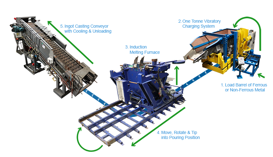
Ferrous & Non-Ferrous Melting & Ingot Casting Production Cell
This machine was installed as part of a production cell at Morgan Advanced Materials UK, comprising of three key machines
- [This machine] Foundry Projects Ltd One Tonne Capacity Mobile Vibratory Charging System
- Induction Heating Systems Limited Induction Melting Furnace - SOLD
- T Masters and Sons Ingot Casting Machine
Specification
One Static Drum Tilter
Consisting of:-Drum Entry Static Frame which is a floor mounted static unit. This will accept the drum from the forklift and has free running rollers to support the drum and allow easy entry into the tilting cradle.
Drum Tilting Cradle
Fabricated from a square hollow section frame with a curved location to accept the drum. There is a set of free running rollers for the drum to sit on and an interlocked latching device. There will be a drum locator in the vertical plane to prevent the drum from moving during the tilting cycle. The tilting frame also forms a chute to discharge the scrap materials into the charging machine. The tilting cradle is raised and lowered by a pair of hydraulic double acting cylinders and there is an on board power pack, control valves and hoses.
One Mobile Furnace Charging Machine
Consisting of:- Main Travel Carriage fabricated from 250 x 150 rectangular hollow section fitted with four single flanged wheels at 250mm diameter on tread, two rear wheels running free, two front wheels fitted with individual motorised geared reduction units complete with disc brakes rated at 0.18kW each. The fixed travel speed is in the region of 10.21 metres/min. The carriage is fitted with four brackets to fit the load cells to. There is a set of festoon cables to supply the controls and interlocks to this moving unit with a junction box at the charger end.
Set Of Load Cell Weighing Equipment
- Four off 2 tonne capacity shear beam load cells
- Four off load cell mounting kits
- One off load cell controller, panel mounted
- One off panel mounted digital display
- One off load cell junction box
- Special screened load cell cable
Weighing Frame
Fabricated from 250mm x 150 rectangular hollow section fitted with four brackets to locate onto the load cells. There are also four heavy brackets to support the vibratory feeder and a further four to accept the main hopper. Jacking screws are fitted to provide a solution in removing a load cell in the event of a failure.
Main Vibratory Feeder Tray
Fabricated from 6mm thick m.s. plate throughout and fitted with an 8mm thick rubber sandwich and 8mm thick steel liner plate in the base, 6mm thick rubber sandwich and 6mm thick steel liner plates to the sides and rear. The feeder is mounted on four pairs of helical coil springs to provide 92 to 95% vibration isolation. Two 2.29 kW out-of-balance motors are used for powering the feeder controlled through an inverter to give variable feed rate control and to allow
D.C. injection for stopping of the motors within 3 to 4 seconds. The feeder is fitted with a bolt on stainless steel discharge chute that is tapered and inclined so as to direct the falling scrap and minimise the amount of damage to the furnace lining.
Main Hopper
Fabricated from 8mm thick m.s. plate for the main body which will be suitably stiffened and ribbed using both 10mm and 12mm plates. Sandwich liners plates will be fitted using 8mm thick rubber and 8mm thick steel. The hopper is supported on four legs from the weighing frame. The hopper sits directly above the vibratory feeder but must not come into contact with it and therefore is static and not included within the vibrating mass. The volumetric capacity is based on a charge density of 6 tonnes/cubic metre.
Common Set of Electrical Equipment
For Parts 1 & 2 including :
- One main control panel to be sited adjacent to the charger.
- One junction box mounted on the charger.
- Two limit switches mounted on the charger for positioning & interlocks.
- Two limit switches mounted on the tilter for positioning & interlocks.
- One safety grab tension wire with two safety switches mounted on the charger.
- One safety nudge bar across the rear of the charger.
- Audible/Visible alarms operating during motion of car.
Description Of Limit Switches and Interlocks
The charger has two lever operated limit switches mounted on the frame, each with a corresponding striker ramp bolted to the platform. One is to position the charger at the rear park position also used for loading the charger and this limit is used as a safety interlock and the other limit switch is to position the charger over the furnace for filling the furnace.
Provision For Interlocks
When the rear park position limit/ramp is activated we have provision in our control panel to provide the furnace controls with a signal from our main control panel to say that the charger is in a safe position allowing the furnace to operate without restriction. If this limit is not made then the charger could be in a position to collide with the furnace. When this happens the furnace must be made that it is not possible to travel or tilt in either direction and the lid cannot open or closed. Once we move back onto our rear park limit/ramp then full controls to the furnace and the lid should be active again.
Before the charger can travel to the furnace we require an interlock signal from the furnace controls to our main control panel to prove that the furnace body is in the correct position to fill and the furnace lid open.
Emergency Stops
- The furnace charger has a pair of safety switches operated with safety tension wire travelling down the two sides and across the rear. These switches are of a re settable type which when operated stops the charger from travelling in either direction.
- There is an emergency stop push button fitted to the main control panel.
- An emergency stop push button is fitted to the remote push button station.
- There is a kickboard at the rear of the charger. This has a proximity type limit switch, which is normally made and indicated so by a light on each proxy. It is normally made for safety reasons and if de-activated i.e. the kickboard depressed then this will stop the charger from travelling.
(The emergency re-set push button is mounted on the fascia of the main control panel)
Dimensions
- Overall: 1620mm x 4600mm x 2320mm
- Feeder Height: 1400mm (height at mouth) x 370mm (width)
- Tipper: 1900mm x 1700mm x 2600mm
- Control Panel: 1500mm x 450mm x 2100mm
![]() Print / Download Foundry Projects Ltd One Tonne Capacity Mobile Vibratory Charging System Datasheet
Print / Download Foundry Projects Ltd One Tonne Capacity Mobile Vibratory Charging System Datasheet
Photographs taken prior refurbishment. Our refurbishment service is not available on all machines.
Machines & equipment for sale
- Surface Treatment
- Cleaning & Degreasing
- Polishing & Belt Linishing
- Mass Finishing
- Ovens & Furnaces
- Process Cooling
- Shot Blasting
- Dust & Fume Extraction
- Air Compressors
- Rectifiers & Transformers
- Miscellaneous
- Latest Stock
- Special Offers
- Direct From Site Clearances
- Auctions
- Brand New Machines
- Available Immediately
- Sell Your Machine
Machine Alert
Get the latest machines emailed directly to you as they become available to buy online. Sign Up Now