Gee and Company Plating / Immersion Treatment Line


Direct From Site Clearance
- Price [?]
- Please call on +44 (0) 1922 45 8000
- Part of a Direct Site Clearance
- Automatic, Immersion Treatments, Multi - Purpose Plating Line
- Condition
- Seen working by RSW, Excellent Condition, Ex demonstration
- Stock No
- PPL500
- Manufacturer
- Gee and Company
- Model
- Straight Line Fully Automatic Plant
- Year of Manufacture
- 2015
- Condition
- Seen working by RSW, Excellent Condition, Ex demonstration
- Work Envelope (WxDxH mm) [?]
- 850 x 1000 x 650
- Process Stages
- 10
- Other Info
- Plant Output: 1 flight bar every 25 Mins
- Location
- Our Central Warehouse, Aldridge, UK
- External Dimensions (WxDxH mm) [?]
- 2000 x 13,500 x 3000
- Delivery Your delivery options
Description
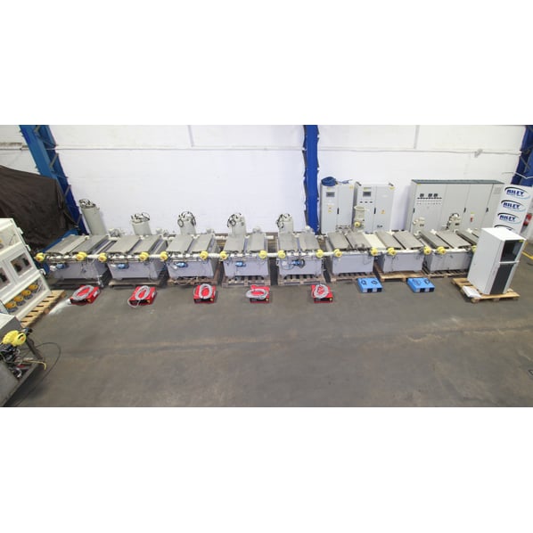
An Unused Plating / Immersion Treatment Line
This Fully Automatic Plating Line was installed at Chromalloy UK's Derby plant and was professional decommissioning by Riley Surface World engineers when the facility was closed.
The plant and ancillaries have been moved to storage and photographed at Riley Surface World's UK facility.
Summary
The line is currently configured for the application of platinum plating on turbine blades this line offers the possibility of conversion to process other high value components due to it’s quality and sophisticated control system. The equipment is arranged in a straight line with the load/unload station at one end for efficiency of operation. The work is carried automatically through the line by an enclosed transporter complete with blow down fans for fume control and motorised raise lower and traverse speed controlled via inverter drives.
General Description
A fully automatic line installed circa 2015 which is in previous condition. Commissioned but never run in production.
The line is currently configured for the application of Platinum Plating on Turbine Blades but offers the possibility of conversion to process other high value components due to it’s quality and sophisticated control system. This represents a rare opportunity to acquire very high value and specification equipment at a fraction of its original cost. Thus, offering any prospective Buyer with an element of ingenuity/resourcefulness a unique opportunity to add value and create an incremental return on initial investment.
The stainless steel transporter system, tanks with automatic lids, solution heating and circulation systems, full SCADA control package have all been observed in operation prior to dismantling for storage and would form the basis of an alternative application as the major building blocks of any line.
It remains of course incumbent on the Buyer to satisfy themselves as with all pre-used process lines that the equipment being purchased meets their requirements and expectations for the future.
The equipment is arranged in a straight line with the Load/Unload station at one end for efficiency of operation. The work is carried automatically through the line by an enclosed transporter complete with blow down fans for fume control and motorised raise lower and traverse speed controlled via inverter drives.
A highly sophisticated supervisory control and data acquisition (SCADA) system is provided incorporating a Siemens PLC linked to a Fujitsu computer running Excelerplate software to provide the man machine interface (MMI).
As to be expected in this precise process, important parameters are carefully monitored and controlled with the resultant information data logged. Solution temperatures for example are controlled to plus/minus one degree celsius and fully automatic dosing is included.
All tanks are provided with actuated stainless steel lids with automatic operation linked to transporter operations.
This represents a unique and rare opportunity to acquire a highly sophisticated line in excellent condition offering considerable savings over the buy new price.
Technical Specification
Plant Design: Straight Line Automatic Plant
Previous Process: Platinum Electroplate
Base Metal of Components: High Strength Super Alloys
Components: Turbine Blades
Operation: Fully Automatic
Estimated Plant Output: One flight bar every 25 minutes
Tank Section: 1000mm wide x 650mm deep
Transporter: One 100kg SWL transporter
Hoist Motor: Variable speed with frequency invertor
Traverse Motor: Variable speed with frequency invertor
Flight Bars: 1 off included
Heating: Electric
Electrical Supply: 415v 50hz 3ph with neutral
Approx. Plant Dimensions:
Length: 13.50 Metres (Excluding Ancillary Equipment)
Width: 2.00 Metres
Height: 3.00 Metres
Principle of Operation
Components are manually loaded onto jigs by an operator and positioned onto a trolley which is located at the front end of the load station ready to be collected by the transporter and transferred through the process as programmed.
The human machine interface unit (HMI) displays current status of system indicating status of all float level controls, solenoid valves, process heating devices, process temperatures, solution conductivities, limit switches, proximity switches, emergency stop circuits, plant alarms etc. which are all controlled.
Each of the five platinum plating tanks are equipped with electrojet external electric tank heaters automatically controlled to manage the chemical temperatures in each tank.
Platinum process plating time is estimated between 60-90 minutes per tank.
When 90% of the total process plating time has elapsed components will be automatically transported back to the load/unload station for inspection.
Plating thickness will be tested to ascertain the plating thickness.
Components will be re-jigged after testing and re-plated to obtain the required thickness.
Each of the five platinum plating tanks are monitored for pH concentration, a fall in pH level will initiate the operation of the associated ammonia reagent dosing pump. Contents monitoring is undertaken via float switch permitting automatic replenishment of levels with DI water from the DI water post dip tank.
Provision is made to automatically dose platinum planting P salts into each of the plating tanks via the operation of the associated P salts dosing pumps. This is from concentration data gained from the associated analyser system.
To contain and control any fumes or steam that may be liberated from the process solutions each of the tanks are fitted with pneumatically actuated lids, automatically controlled by the PLC programme to open and close when flight bars are being loaded or removed from the tank.
Tank mounted lip extraction ducts permit drawing off excessive levels of chemicals to the pump sump.
The maximum efficiency of the fume extraction when tank lids are open to allow flight bar movement into or out of process tanks extraction rate will be increased by adjustment of the associated pneumatically actuated damper.
The pre-plate ultra-sonic tanks are monitored for pH concentration, a fall in pH level will initiate the operation of the associated ammonia reagent dosing pump.
Both pre-plate ultra-sonic tanks contents are heated by electrical pan heaters, contents levels are monitored by integral float switches and tank contents agitated by externally mounted recirculation pumps. Contents monitoring is undertaken via float switches permitting automatic replenishment of levels with DI water from the DI water feed.
Both DI water post dip tanks are equipped with electrojet external electrical tank heaters with automatic control to manage the contents and temperatures in each tank, contents levels are monitored by integral float switches and tank contents agitated by externally mounted recirculation pumps. Contents monitoring in undertaken via float switch permitting automatic replenishment of levels with DI water from the DI water feed.
Off Line Components Loading/Unloading
Components are received from the preparation area prior to being processed through the auto plating facility.
Mobile trolleys are used to support flight bars onto which components and anodes are attached. Each component has a unique bar code/part ID.
When a flight bar is loaded with components and presented at the load/unload station the hand held barcode reader is used by the operator to register the identity of the flight bar and components and data feedback to the PLC control system.
This will be achieved by the operator manually scanning in the barcodes with his bar-code reader or manual entering the code on the HMI interface keyboard and recorded on paperwork accompanying the batch of parts.
This information will be used to determine the precise process requirements of the load and, on completion of the process routine, the system database will store historical data for individual parts for future traceability requirements.
The plant PLC control system is required to check the historical/SQL database as each part is scanned into the system, to prevent a part being processed more than once through the plating facility.
Once the component or flight-bar has been scanned then the operator selects a process sequence for the flight bar that is not permitted, a warning dialogue box will appear on the workstation screen.
At this point, the operator must either, remove the offending part(s) and re-scan the remainder, or an authorised person may log-on and override the restriction. If the latter action is taken, the database must record the action against the individual blade(s).
Specification of equipment
Station No.1: Load/Unload Station
- 1 off Loading Trolley constructed in Stainless Steel.
Stage will be fitted with:
- 1 Set Fixed guides with proximity detectors for sensing trolley “in station condition”.
- 1 Set Polypropylene flight bar location brackets.
Station No. 2 Process DI Water Post Dip
- Temperature: 40°C.
- 1 Off Single compartment polypropylene tank of internal size 850 x 1000 x 650mm deep, complete with top flange.
- The body of the tank will be manufactured from material supported with additional strengthening.
- Tank lagged externally.
- The tank will be raised off the floor by stainless steel support stand.
Tank will be supplied with:
- 1 Set Electric heating equipment complete with protection and control, contactors RCD and MCB units.
- 1 Set Solution level switches for alarms and heater protection.
- 1 Set Process temperature control (one hard wired safety watchdog and one through PLC).
- 1 Set Polypropylene flight bar location brackets.
- 1 Set Water supply with manual on/off isolation valve and level control for auto top-up.
- 1 Set Actuated stainless steel lids.
- 1 Set Eductor agitation.
- 1 Set Siebec filtration.
Station No. 3 Process DI Water Post Dip
- Temperature: 40°C.
- 1 Off Single compartment polypropylene tank of internal size 850 x 1000 x 650mm deep, complete with top flange.
- The body of the tank will be manufactured from material supported with additional strengthening.
- Tank lagged externally.
- The tank will be raised off the floor by stainless steel support stand.
Tank will be supplied with:
- 1 Set Electric heating equipment complete with protection and control, contactors RCD and MCB units.
- 1 Set Solution level switches for alarms and heater protection.
- 1 Set Process temperature control (one hard wired safety watchdog and one through PLC).
- 1 Set Polypropylene flight bar location brackets.
- 1 Set Water supply with manual on/off isolation valve and level control for auto top-up.
- 1 Set Actuated stainless steel lids.
- 1 Set Eductor agitation.
- 1 Set Siebec filtration.
Station No. 4 Process Pre-Plate Ultrasonic
- Temperature: 50°C.
- 1 Off Single compartment polypropylene tank of internal size 850 x 1000 x 650mm deep, complete with top flange.
- The body of the tank will be manufactured from material supported with additional strengthening.
- Tank lagged externally.
- The tank will be raised off the floor by stainless steel support stand.
Tank will be supplied with:
- 1 Set Electric heating equipment complete with protection and control, contactors RCD and MCB units.
- 1 Set Solution level switches for alarms and heater protection.
- 1 Set Process temperature control (one hard wired safety watchdog and one through PLC).
- 1 Set Polypropylene flight bar location brackets.
- 2 Off Submersible ultrasonic transducers across each side of tank to operate timed on flight bar presentation. Power level 2000 watts per side.
- 1 Set Water supply with manual on/off isolation valve and level control for auto top-up.
- 1 Set Actuated stainless steel lids.
- 1 Set Eductor agitation.
- 1 Set Siebec filtration.
- Tank is extracted from both sides.
Station No. 5 Process Pre-Plate Ultrasonic
- Temperature: 50°C.
- 1 Off Single compartment polypropylene tank of internal size 850 x 1000 x 650mm deep, complete with top flange.
- The body of the tank will be manufactured from material supported with additional strengthening.
- Tank lagged externally.
- The tank will be raised off the floor by stainless steel support stand.
Tank will be supplied with:
- 1 Set Electric heating equipment complete with protection and control, contactors RCD and MCB units.
- 1 Set Solution level switches for alarms and heater protection.
- 1 Set Process temperature control (one hard wired safety watchdog and one through PLC).
- 1 Set Polypropylene flight bar location brackets.
- 2 Off Submersible ultrasonic transducers across each side of tank to operate timed on flight bar presentation. Power level 2000 watts per side.
- 1 Set Water supply with manual on/off isolation valve and level control for auto top-up.
- 1 Set Actuated stainless steel lids.
- 1 Set Eductor agitation.
- 1 Set Siebec filtration.
- Tank is extracted from both sides.
Station No.6 Process Platinum Electroplate
- Temperature: 88°C.
- 1 Off PVDF tank of internal size 850 x 1000 x 600mm deep, complete with top flange and internal weir. Solution level will be maintained by the plate weir.
- The body of the tank will be manufactured from material supported with additional strengthening.
- The tank will be raised off the floor by stainless steel support stand.
Tank will be supplied with:
- 1 Set Electric heating equipment complete with protection and control, contactors RCD and MCB units.
- 1 Set Solution level switches for alarms and heater protection.
- 1 Set Process temperature control (one hard wired safety watchdog and one through PLC).
- 1 Set Flight bar DC contact brackets mounted on a reciprocating framework with horizontal movement.
- 1 Set Anode bars.
- 1 Off Constant current power supply rated at 10VDC x250 amps.
- 1 Set Solution dosing equipment based on automatic monitoring of process.
- 1 Set Water supply with manual on/off isolation valve and level control for auto top-up.
- 1 Set Actuated stainless steel lids.
- 1 Set Eductor agitation.
- 1 Set Siebec filtration.
- Tank is extracted from both sides.
Station No.7 Process Platinum Electroplate
- Temperature: 88°C.
- 1 Off PVDF tank of internal size 850 x 1000 x 600mm deep, complete with top flange and internal weir. Solution level will be maintained by the plate weir.
- The body of the tank will be manufactured from material supported with additional strengthening.
- The tank will be raised off the floor by stainless steel support stand.
Tank will be supplied with:
- 1 Set Electric heating equipment complete with protection and control, contactors RCD and MCB units.
- 1 Set Solution level switches for alarms and heater protection.
- 1 Set Process temperature control (one hard wired safety watchdog and one through PLC).
- 1 Set Flight bar DC contact brackets mounted on a reciprocating framework with horizontal movement.
- 1 Set Anode bars.
- 1 Off Constant current power supply rated at 10VDC x250 amps.
- 1 Set Solution dosing equipment based on automatic monitoring of process.
- 1 Set Water supply with manual on/off isolation valve and level control for auto top-up.
- 1 Set Actuated stainless steel lids.
- 1 Set Eductor agitation.
- 1 Set Siebec filtration.
- Tank is extracted from both sides.
Station No.8 Process Platinum Electroplate
- Temperature: 88°C.
- 1 Off PVDF tank of internal size 850 x 1000 x 600mm deep, complete with top flange and internal weir. Solution level will be maintained by the plate weir.
- The body of the tank will be manufactured from material supported with additional strengthening.
- The tank will be raised off the floor by stainless steel support stand.
Tank will be supplied with:
- 1 Set Electric heating equipment complete with protection and control, contactors RCD and MCB units.
- 1 Set Solution level switches for alarms and heater protection.
- 1 Set Process temperature control (one hard wired safety watchdog and one through PLC).
- 1 Set Flight bar DC contact brackets mounted on a reciprocating framework with horizontal movement.
- 1 Set Anode bars.
- 1 Off Constant current power supply rated at 10VDC x250 amps.
- 1 Set Solution dosing equipment based on automatic monitoring of process.
- 1 Set Water supply with manual on/off isolation valve and level control for auto top-up.
- 1 Set Actuated stainless steel lids.
- 1 Set Eductor agitation.
- 1 Set Siebec filtration.
- Tank is extracted from both sides.
Station No.9 Process Platinum Electroplate
- Temperature: 88°C.
- 1 Off PVDF tank of internal size 850 x 1000 x 600mm deep, complete with top flange and internal weir. Solution level will be maintained by the plate weir.
- The body of the tank will be manufactured from material supported with additional strengthening.
- The tank will be raised off the floor by stainless steel support stand.
Tank will be supplied with:
- 1 Set Electric heating equipment complete with protection and control, contactors RCD and MCB units.
- 1 Set Solution level switches for alarms and heater protection.
- 1 Set Process temperature control (one hard wired safety watchdog and one through PLC).
- 1 Set Flight bar DC contact brackets mounted on a reciprocating framework with horizontal movement.
- 1 Set Anode bars.
- 1 Off Constant current power supply rated at 10VDC x250 amps.
- 1 Set Solution dosing equipment based on automatic monitoring of process.
- 1 Set Water supply with manual on/off isolation valve and level control for auto top-up.
- 1 Set Actuated stainless steel lids.
- 1 Set Eductor agitation.
- 1 Set Siebec filtration.
- Tank is extracted from both sides.
Station No.10 Process Platinum Electroplate
- Temperature: 88°C.
- 1 Off PVDF tank of internal size 850 x 1000 x 600mm deep, complete with top flange and internal weir. Solution level will be maintained by the plate weir.
- The body of the tank will be manufactured from material supported with additional strengthening.
- The tank will be raised off the floor by stainless steel support stand.
Tank will be supplied with:
- 1 Set Electric heating equipment complete with protection and control, contactors RCD and MCB units.
- 1 Set Solution level switches for alarms and heater protection.
- 1 Set Process temperature control (one hard wired safety watchdog and one through PLC).
- 1 Set Flight bar DC contact brackets mounted on a reciprocating framework with horizontal movement.
- 1 Set Anode bars.
- 1 Off Constant current power supply rated at 10VDC x250 amps.
- 1 Set Solution dosing equipment based on automatic monitoring of process.
- 1 Set Water supply with manual on/off isolation valve and level control for auto top-up.
- 1 Set Actuated stainless steel lids.
- 1 Set Eductor agitation.
- 1 Set Siebec filtration.
- Tank is extracted from both sides.
Transfer through process stations
Transporter Equipment
1 Off Fully motorised 100kg SWL Robotic transporter system, to operate in three modes.
Mode 1 Fully Automatic
Where all traverse and hoist movements automatically follow pre-set routes and process times. Either in fixed time way or random control.
Mode 2 Semi-Automatic
Where all robotic transporter movements are under the control of the operator via a pendant or joystick or keyboard control
Mode 3 Maintenance
A ‘Works Engineer’ manual mode which is key or code lockable via the control panel. When in this mode, the transporter may be stopped in any position ‘off station’, i.e. for maintenance purposes.
Transporter Operation
The following description applies to the Automated Platinum Plating Transporter operation at the Load/Unload Station but generally applies to all stations. The transporter will run on a free standing runway in accordance with EN ISO 9001:2008. This will be complete with a 500 Kg 0.37 KW traverse and a 100Kg hoist motors.
The transporter has 3 operating modes, selected via the control unit with Emergency Stop function and operating modes, Fully Automatic (AUTO), Semi-Automatic (SEMI-AUTO) and Maintenance Mode (MANUAL
SEMI-AUTO Mode
All transporter movements are initiated by the operator using a manual pendant control unit and will be controlled and monitored by the PLC, to ensure that all safety interlocks remain active. For example, pressing the forward button on the pendant will cause the transporter to move forward at normal speed until the button is released. At this point the transporter will immediately ramp down to creep speed and will continue to move forward until it reaches the next station flag, where it will stop automatically when both station proximity switches are in contact with the flag. However, striking over travel limit switches at any time will stop the travel or hoist motor.
MANUAL Mode
All transporter movements are initiated by the operator using the manual pendant control and all travel and lift movements are carried out at creep speed for as long as the respective buttons are pressed (failsafe dead man’s handle operation) or until a fixed, end of travel, stop bracket is reached. In this mode there are no active safety or control interlocks, which enables the operator or maintenance personnel to recover from collisions etc.
AUTO and SEMI-AUTO Modes
Personnel protection is provided by a removable guards spanning the complete length of the operator side of the transporter. If the light guard is activated any time with an obstruction, all motive power to the transporter will be removed immediately. Audible and visual alarms will also be generated. Once the fault has been rectified, the system can be reset, and the transporter can be restarted.
There is an emergency stop push button mounted on the manual control pendant and an emergency stop light guard is installed along the entire length of the line at tank top level, which, when operated, will immediately cut all motive power to the transporter, and generate audible and visual alarms. Once the fault has been rectified, the system can be reset, and the transporter can be restarted.
Station Identification Proximity Switches are fitted on the far side of the Transporter carriage to identify which specific station the Transporter is on using binary code system.
The transporter upper framework is enclosed by a transparent canopy to prevent steam or fumes being released into the shop environment when loads are being transferred between tanks.
The canopy is fitted with two low energy axial flow pressurisation fans These fans operate automatically and will run continuously whilst the transporter is operating in Auto and Semi-Auto modes to pressurise the canopy with shop air, which works in conjunction with the tank-mounted lip extraction ducts to minimise the accumulation of steam and/or fume within the canopy, i.e. when the transporter is positioned above a lidded tank and the lids open to allow a flight bar to be loaded into or removed from the tank, any steam/fume liberated from the tank or components is pushed towards the lip extract ducts and is routed to the fume extraction scrubber.
The robotic transporter has features as follows:
- The traverse drive is by means of a variable speed motor and gear box under the control of a frequency inverter designed to give a smooth accelerating and decelerating speed ramp.
- The hoist mechanism is by means of a variable speed motor and gear box under the control of a frequency invertor designed to give a smooth accelerating and decelerating speed ramp.
- Anti-collision and over-run switches are fitted.
- Anti-lowering switches are incorporated on the transporter to stop one flight bar being lowered on top of another.
Track Support Structure
The track is manufactured from stainless steel beams supported by stanchions from the floor. Cross bracing is provided as required.
The self-supporting structure is in bolted sections lined and levelled on to the factory floor without the need for special foundations.
The complete structure is manufactured from stainless steel suitable for the operating environment.
Drip Shields
Tanks not fitted with exhaust ducts have PP drip shields in between to stop solution spillage.
Automatic Dosing For Platinum Processes
The platinum electroplate stations are provided with automatic dosing as detailed in the principles of operation above.
Fume Exhaust System
The extraction system includes the following major items of equipment:
- Fume exhaust hoods
- Exhaust dampers
- Interconnecting trunking
Fumes are extracted via lip hoods at low level, into a plenum chamber and onwards through riser ducts into a manifold running at high level at the rear of the plant. The duct manifolds are fitted with removable access doors to enable internal cleaning and removal of any chemical residues for reclaim.
Specification of equipment
Item 1 - Lip Extract Ducts -
- Lip extraction ducts fitted above tank flange with full length capture slots and removable access door for cleaning purposes.
- Material of Construction - Polypropylene
Item 2 - Ductwork -
- Flange connection risers to main manifold.
- All ductwork supplied complete with supports, hangers, brackets, fasteners and fixings.
- Material of construction - Polypropylene
Control Console
The central control console is located adjacent to the load/unload area.
Electrical Wiring
All electrical wiring between the central control console and field electrical items is installed in corrosion resistant PVC or stainless-steel trunking suitably supported.
Mechanical Services
One set mechanical services serving the previously described plant complete with all necessary supports and brackets.
Maintenance and Operation manuals
Hard and electronic copies of the available manuals have been provided by Chromalloy.
![]() Print / Download Gee and Company Plating / Immersion Treatment Line Datasheet
Print / Download Gee and Company Plating / Immersion Treatment Line Datasheet
Additional files
Photographs taken prior refurbishment. Our refurbishment service is not available on all machines.
Machines & equipment for sale
- Surface Treatment
- Cleaning & Degreasing
- Polishing & Belt Linishing
- Mass Finishing
- Ovens & Furnaces
- Process Cooling
- Shot Blasting
- Dust & Fume Extraction
- Air Compressors
- Rectifiers & Transformers
- Miscellaneous
- Latest Stock
- Special Offers
- Direct From Site Clearances
- Auctions
- Brand New Machines
- Available Immediately
- Sell Your Machine
Machine Alert
Get the latest machines emailed directly to you as they become available to buy online. Sign Up Now