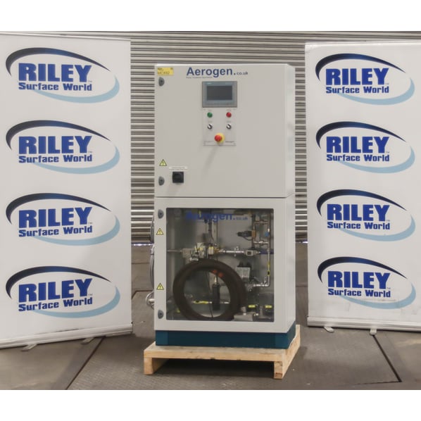
Aerogen Flame Treatment System


- Stock No
- MC892
- Manufacturer
- Aerogen
- Model
- FTAUTO-FC-ASSY-01
- Year of Manufacture
- 2017
- Serial
- 36371
- Condition
- From a working environment, Excellent Condition
- Other Info
- Fuel - Natural Gas
- Location
- Royston, Cambridgeshire UK
- Weight (kgs)
- 150 kg
- External Dimensions (WxDxH mm) [?]
- 900 x 350 x 1710
- Delivery Your delivery options
Description
Aerogen flame treatment system increases adhesion for painting, bonding, slushing and foaming and is commonly and increasingly used within vehicle manufacture. Aerogen technology is utilized on components used in almost every type of automotive vehicle in the marketplace today.
Flame Treatment Benefits
- In all instances, flame treatment offers superior results to other methods such as corona or plasma.
- Flame treatment offers higher treatment levels and no decay of treatment.
- The treatment level remains virtually indefinitely.
- Both process and economic advantages.
Applications of Flame Treatment
- Automotive - For painting and bonding of car bumpers and instrument panels etc.
- Converting/Printing - Web treatment or conditioning improves adhesion for laminating, coating and printing.
- Plastics - Flame treatment offers enhanced adhesion solutions for cups, caps, cables and containers when printing or labelling.
- Film - Printing for gift wrapping, confectionery, snack foods etc.
- Bakery - Baking of bread, cakes, pizzas, biscuits and searing or branding.
Implementing flame treatment will enhance product quality and durability, leading to a reduction in raw materials, waste and overall manufacturing costs. Due to the efficient low cost gas consumption, savings in the production process can be measured immediately.
Flame Treatment of Plastic Substrates for Adhesive Bonding
Obtaining an adequate bond strength when bonding plastic-to-plastic substrates or plastic to dissimilar substrates is often a challenge for resin systems. In general plastic surfaces demonstrate poor ‘wettability’ or the ability of a liquid to form a continuous film.
These types of substrates or are called LSE or Low Surface Energy substrates and typically thermoplastic surfaces fall with in this category.
Teflon* or its generic name PTFE and other polyethylene derivatives such as HDPE, LDPE, UHMW and olefinic-based plastics demonstrate poor liquid wettability due to its low surface energy. To create a viably bondable surface condition to these types of plastics, it must be surface treated by creating a superficial oxidized surface to increase its dynamic surface tension. Various types of physical treatment can be used to increase the surface energy of plastics, mostly through oxidation of the superficial layer.
Flame treatment is the most widely used and cost effective pre-treatment for polyethylene (HDPE, LDPE, UHMW) and polyolefin based plastics prior to polymer bonding or printing. It consists of exposing the surface to be coated to a suitable oxidizing flame for a short period of time (0.2 to 3 sec.).
The resulting change of the surface by creating an oxidized surface greatly improves the ability of the liquid to wet-out the surface thus creating a strong adhesive bond between the surface and the coating.
A Flame Treating process consists of exposing the surface to a suitable oxidizing flame for a period in the range 0.2 to 3.0 seconds. This treatment brings about a change to the polymer surface that increases its surface energy allowing fluids to effectively wet-out the surface and permitting a strong adhesive molecular and mechanical bond.
Technical Description
Burner Section
- This section flame plasma treats the product and is manually adjustable to obtain the desired treatment.
- The flame plasma burner can be either permanently mounted or manually operated.
- The flame is ignited by a transformer and ignition electrode.
Control System Cabinet
The Control System Cabinet is made up of two sections, the Mixture Generator Section and the Electrical Section which are protected by key lock doors. These doors MUST always be kept locked and the key/s must be kept in the possession of a trained or qualified staff member who is aware of the residual risks on the equipment. Under no circumstances should the keys be left in the doors.
Mixture Generator Section
This section contains the flow meter, gas safety valves, Venturina mixer, pressure regulators, pressure switches, proportional valve and other ancillary components necessary for burner operation. All electrically operated and controlled devices are wired to the electrical section.
Gas Pipework
- Refer to “Mechanical Assembly” in paragraph 16 of the Manual.
- The Gas is supplied to the cabinet through a ball valve (10) then it flows through gas filter (11) and regulator (12) and then a low gas pressure switch (14) which verifies if the gas pressure is above the operating limit.
- Next the gas flows to the pressure gauge (15)and flow tube meter (13).
- After the flow meter (13) the gas passes through the safety solenoid valves (16 &17) controlled by the fail safe PLC and then the high pressure switch(18).
- Next the gas splits into two lines, first-the proportional gas valve (20) and second-micro metre needle valve (19).
- The gas then continues through the second micro metre needle valve (21)and ball valve (22) before entering the uni-mixer (Item90)
- The ball valve (22) isolates the gas supply from the mixture pipework and allows the user to perform two tests, a drop test on the gas supply pipework and during initial start-up a burner fault interlock test
Air Pipe-work
- Compressed air from the ball valve (60) passes through the air filter (61). It is then regulated down from the supply pressure (4-8 bar) to about 3 bar by the air regulator (61). After passing through the regulator the air pressure is monitored by the air pressure switch (61).
- It then passes through the solenoid valve (61) to flow meter (65) and then the needle valve (66) that allows manual adjustment of the amount of air within the system.
- After the needle valve (66) air passes to the uni-mixer (90).
- The burner output is controlled by varying the amount of airflow across the uni-mixer. This is achieved by adjusting the needle valve (66).
Mixture Pipework
Mixing of the air and gas occurs in the uni-mixer (90) which has a calibrated air jet. As airflows through the uni-mixer, creating suction on the gas line using the venturi principle. The quantity of gas flow depends on the setting of the second micrometre needle valve (Item 21), the suction produced by the flow of air through the venturi section of the uni-mixer and also the pressure that is present in the mixture line.
The air/gas mixture proceeds after the mixture proving pressure switch (Item92) which during start-up verifies that sufficient airflow is present for purging the system, and also during normal operating conditions proves that the mixture pressure is above the operating limit to the pressure gauge (91) then via the flexible hose to the flame-treating burner.
Electrical Section
- The electrical cabinet contains the safety pic, flame safety pic modules, normal pic modules, switches and other control equipment.
- The burner safety is controlled by a safety pic and flame detector.
- The safety pic controls the start-up sequence and gas trim control. It also monitors interlocks necessary for correct operation.
- A Human Machine Interface (HMI) panel is located on the doors of the electrical section and allows the user to adjust settings for the equipment.
- Located on these doors is the Operator Panel with buttons to control the equipment and also an emergency-stop button.
![]() Print / Download Aerogen Flame Treatment System Datasheet
Print / Download Aerogen Flame Treatment System Datasheet
Photographs taken prior refurbishment. Our refurbishment service is not available on all machines.
Machines & equipment for sale
- Surface Treatment
- Cleaning & Degreasing
- Polishing & Belt Linishing
- Mass Finishing
- Ovens & Furnaces
- Process Cooling
- Shot Blasting
- Dust & Fume Extraction
- Air Compressors
- Rectifiers & Transformers
- Miscellaneous
- Latest Stock
- Special Offers
- Direct From Site Clearances
- Auctions
- Brand New Machines
- Available Immediately
- Sell Your Machine
Machine Alert
Get the latest machines emailed directly to you as they become available to buy online. Sign Up Now